
Guide to Measuring a Driveshaft
HOW TO MEASURE FOR YOUR DRIVESHAFT
This page will help you determine the information needed to order our Custom Engineered Driveshafts. You will need:
- Transmission type
- Rear U-Joint Series
- Shaft measurement
STEP 1: IDENTIFY TRANSMISSION
The first thing that you’ll need to do is to identify your transmission.
Chrysler – Dodge
727 – 30 Spline 1 11/16″ Seal Diameter
904 – 26 Spline 1 9/16″ Seal Diameter
Ford
C6-T56 – 31 Spline 1 11/16″ Seal Diameter
AOD & C4 & T5 – 28 Spline 1 1/2″ Seal Diameter
4 R 7OW – 28 Spline 1.598″ Seal Diameter
General Motors
T-350 700R4-4LLOE – 27 Spline 1 1/2″ Seal Diameter
T-400-4L80E – 32 Spline 1 7/8″ Seal Diameter
For T-400, 4L80, 4L85 and 6L80 Transmissions: We will need to know if your 32 spline Output Shaft is drilled and tapped (has a threaded hole in the end).
Note: Transmission slip yokes are manufactured with various U-Joint Series. It is important to match Horsepower and Torque requirements to U-Joint Series. For aftermarket transmission applications usually a spline count and seal diameter will identify slip yoke required.
STEP 2: IDENTIFY REAR U-JOINT
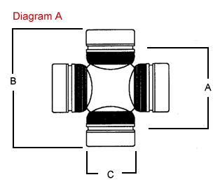
The next thing that you’ll need is to identify is your rear U-Joint. To do that, you’ll need to measure the “Cup Diameter” of the joint, as well as the length of the joint. We strongly recommend that you make your measurement using a set of digital calipers, since deviations as small as 1/16” can call for a different joint.
There are hundreds of Universal Joints sizes (U-Joints) or “Series” to accommodate many different applications of power and desired longevity for your automotive, 4×4 truck or auto racing requirements. However, these 4 series of joints cover most needs.
1310 Spicer Series:
- 1 1/16″ Cup Diameter (see Diagram A — Dimension C below)
- 3 7/32″ Length (see Diagram A — Dimension B below)
- Certain Ford applications have 2 cups 1 1/8” diameter. Appropriate horsepower range is up to 500 in circle track or road racing, small tire drag racing and 4×4.
- Also available: Performance Dynamic Cryo Joint.
1330 Spicer Series:
- 1 1/16″ Cup Diameter (see Diagram A — Dimension C below)
- 3 5/8″ Length (see Diagram A — Dimension B below)
- Certain Ford applications have 2 cups 1 1/8” diameter. Slightly stronger than 1310. Used in 5.0 Mustangs.
- Also available: Performance Dynamic Cryo Joint.
3R Saginaw Series:
- 1 1/8″ Cup Diameter (see Diagram A — Dimension C below)
- Retained with internal clip 2 5/8″ (see Diagram A — Dimension B below)
- Most common GM joint. Horse power range up to 700 in road racing and circle track. Solid drag racing U-Joint can accommodate most sportsman classes.
- Also available: Performance Dynamic Cryo Joint.
1350 Spicer Series:
- 1 3/16″ Cup Diameter (see Diagram A — Dimension C below)
- 3 5/8″ Length (see Diagram A — Dimension B below)
- Manufactured with OEM tolerances and treated with our Cryogenic Process to yield the strongest U-Joint available. For drag racing applications a solid non-lube design U-Joint is recommended because of the tremendous initial shock load, or short duration of high torque the joint must be able to withstand.
The following diagrams may be helpful to you as well.
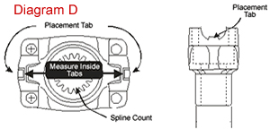
If Pinion Yoke has Placement tabs that retain the U-Joint, measure inside tabs. See Diagram D.
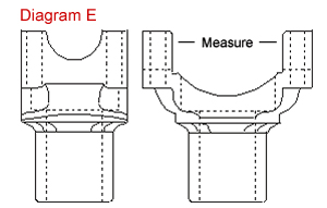
If Pinion Yoke does not have Placement Tabs that retain U-Joint, measure from flat of yoke inside to inside. See Diagram E.
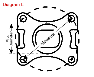
If 4 bolt Flange is used on pinion, measure Pilot Diameter and center to center diagonally bolt hole to bolt hole. See Diagram L.
STEP 3: DRIVESHAFT MEASUREMENT
The Driveshaft Measurement is the “holy grail” of the measurements that we need. While a U-Joint or slip yoke can be swapped out, in most cases the length of the driveshaft once built can not be altered (it can only be shortened, and even then it is not always possible). It is very important for us to have the correct driveshaft length measurement before starting production on your shaft. Please make sure that you measure twice.
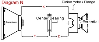
If Bully Driveline is supplying you with a transmission slip yoke, then we will need Dimension “X” in the Diagram above. This is the measurement from the seal of the transmission to the face of the pinion yoke/flange. See Diagram N above. This measurement must be made with the car at ride height, and if you have a “rubber boot” on the end of your transmission make sure you measure all the way into the transmission seal.
If Bully Driveline is supplying you with a transmission slip yoke and pinion yoke, then we will need Dimension “W” in the Diagram above. This is the measurement from the seal of the transmission to the pinion seal.
If you are ordering a 2-piece driveshaft, then we will need Dimension Y and Dimension Z in the Diagram above.
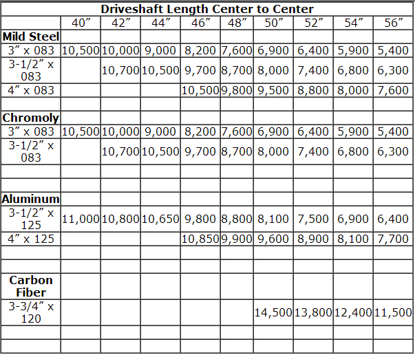
CRITICAL SPEED CHART
Critical Speed is the RPM at which the driveshaft is computer projected to bend or whip. See below for our Critical Speed Chart, which shows the maximum RPM broken down by length of shaft and by material of the shaft. You will see that there is increasing strength from Steel/Chromoly to Aluminum, and from Aluminum to Carbon Fiber at every driveshaft length. Please make sure that you are building a driveshaft that will withstand the maximum RPM of your vehicle.
CRITICAL SPEED CHART
Critical Speed is the RPM at which the driveshaft is computer projected to bend or whip. Exceeding Critical Speed can produce vibrations that can result in driveshaft failure.
The vibrations can also cause damage to the differential gears and bearings. The transmission extension housing, along with the torque converter and planetary gears can also be destroyed.
When you take a small piece of steel and bend it repeatedly, the stress will eventually break the steel. The same effect occurs on your complete driveline when no attention is paid to Critical Speed.